Estonia
NMIS – Software for Aids to Navigation management and operations in Estonia
Total number of Aids to Navigation in Estonia is 1628, of them 323 (20%) being fixed AtoN and 1305 (80%) floating AtoN. 55 (17%) of our fixed AtoNs are lighthouses. 49% of the AtoNs are managed by the Estonian Transport Administration (ETA), the remaining 51% belong mainly to private ports.
After regaining independence, Estonia also took over Aids to Navigation from the Hydrographic Service of the Soviet Navy in 1993. What was not directly dilapidated was in poor condition and far from being modern in the context of the time. The same year, the Estonian Maritime Administration, together with its industrial partner, Cybernetica AS, started developing its own AtoN concept, according to which new lighting devices and data transmission devices for lighthouses and buoys were developed (under brand name EKTA) from scratch, and the architecture of the entire system designed. According to the concept, the AtoN had to have a local area network and data communication between an AtoN and the data center in the NMT mobile network. NMT (Nordic Mobile Telephone) monitoring was quickly replaced with GSM (Global System for Mobile Communication) and after some time with LTE (Long Term Evolution). The data communication network was to ensure the control and monitoring of the status of the AtoNs.
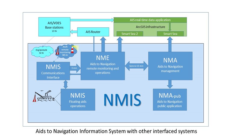
Since 2007, focus has turned from hardware development mostly to the development of the Aids to Navigation Information System (NMIS). The Information System offers software support for managing the data of Aids to Navigation and organizing maintenance of the Aids to Navigation, from buoy equipment weighing tons to setting up the electronic equipment located on the AtoN. NMIS is interfaced with several other systems, including the AIS shore network, GIS applications and the State Information System[1].
Aids to Navigation Information System (NMIS) and AtoN data management
All of Estonia’s Aids to Navigation related information is managed in the NMIS. The part of the information system that allows managing the life cycle of AtoNs as entities in a database (carrying out the procedures for creating new AtoN, changing data and status of existing AtoNs, as well as discontinuing them) online is called Aids to Navigation Database (NMA) and, in some context, AtoN management application. Only authorized and authenticated users can access the NMA. This information system manages both physical and digital AtoN (synthetic AIS AtoN and virtual AtoN), and also leading lines as systems of AtoNs.
Public version of the NMA
A separate public database application with its own web interface is associated with the AtoN management application, which allows making inquiries for lists of AtoNs and view (limited) data about AtoNs. Dataset of the public database is formed on basis of the dataset of the database of AtoN management application and updated periodically (four times per hour).
Remote monitoring of Aids to Navigation
All lighted buoys (185 pcs) and almost all of the fixed AtoNs managed by the ETA (196 pcs) are equipped with a mobile network based communication solution, which allows sending monitoring reports on operation of the AtoNs and operational status of the equipment periodically to NMIS data hub. Remote monitoring is the key part of the NMIS allowing checking and controlling operation of AtoN equipment and preventing failures.
The electronic equipment necessary for operation of AtoNs is in local network with the communication controller of the AtoN, which prepares and transmits monitoring reports. The communication controller and other devices can be remotely managed and their firmware can updated remotely via the NMIS communication interface. In addition to the usual scheduled reports, special data inquiries can made and different periodical data communication status reports can arranged.

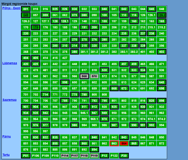
Status form of remotely monitored AtoNs in the NME user interface (different colours indicate different status of the AtoNs)
Several of the remotely monitored buoys have MMSI (Maritime Mobile Service Identity) number, and these buoys are represented on ECDIS displays as synthetic AIS AtoNs. Such buoys send a status report every three minutes, and when the report arrives to NMIS, NMIS prepares a message with the data of the buoy for AIS router that will broadcast the message to the AIS Network. The AtoN displayed as an additional layer on the electronic chart, where the buoy’s actual position can be seen and its detailed data inquired.
Virtual AtoN
NMIS also includes support for managing virtual AtoNs (design, activation, monitoring, deactivation and canceling). There are no virtual AtoNs used in Estonia yet but testing in progress and then virtual AtoNs are taken into use, as necessity comes.
Virtual AtoN are planned to be used e.g. when there is a need for quickly marking a new danger or in places where physical AtoN cannot be used for some reason (e.g. due to too great depth). Also they can be used for indicating missing of a buoy from its designated location or in the event the buoy has drifted away, e.g. due to broken chain.
Operations with floating [2]
Work with floating aids in Estonian Transport Administration is almost entirely organized using NMIS. NMIS contains a database of all means of equipment for floating aids (lanterns, hulls, counterweights, batteries, chains, anchors), from which equipment sets for specific AtoN are compiled in the information system.

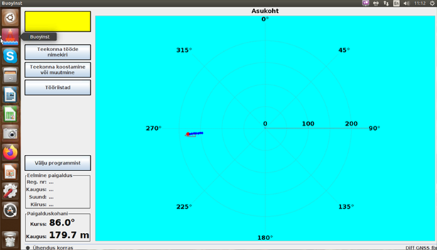
Shipmaster’s buoy works tool – buoy installation software installation target board[3]
Based on this data, work orders are drawn up for specific buoy ship, based on which the cargo taken to the ship is assembled at the buoy yard. Work orders are prepared on basis of planning logic, which may not always match the logic of the shipmaster’s work process, therefore shipmasters have the opportunity to prepare the most suitable itinerary for a specific situation from the work orders (the itinerary can also consist of different types of floating aids operations originating from different work orders).
The floating aids operations support software helps the shipmaster to install floating aids with high precision in the intended place. The shipmaster does not need to know the coordinates of the location of the buoy, they are included with the work order, and based on them, software draws the coordinated target on the shipmaster’s screen. The shipmaster’s task is to maneuver the ship so that the boom of the crane holding the anchor of the floating aid is exactly in the middle of the target, signal the assistants to release the anchor and to confirm the installation by pressing a key on the keyboard.
The position of the installed anchor is recorded as the actual position of the buoy anchor in NMIS database and it also reports an error in the installation work. If the error is smaller than allowed, the buoy considered correctly installed and the installation status of the buoy is automatically changed in NMIS (also installation time is recorded). If the installation does not succeed with the required accuracy, then the installation has to be repeated. If it is still not possible to achieve the required accuracy, the work must approved or rejected in the NMIS by the customer. NMIS data is also basis for changes in other information systems – chart corrections, navigation warnings, etc.
Interfacing of NMIS with other systems
NMIS contains spatial data, but structurally NMIS is not a Geoinformation System. NMIS is interfaced with GIS applications, serving as a source of input data for them. The most important GIS application is the public web application Nutimeri (literally Smart Sea)[4], which, among other layers, displays data layers of AtoNs managed in NMIS, against the background of navigation charts, other charts or aerial photos. In addition, there is a GIS application with authentication, Nutimeri 2, which is the NMIS GIS interface for the specialists of the Transport Administration to visualize spatial data of NMIS and work with it.
In order to provide AIS-based AtoN service, NMIS is interfaced with AIS/VDES base stations by AIS router. An ArcGIS application of the AIS data stream (also visible in Nutimeri), developed primarily for displaying ship positions in real-time, displays, among other AIS objects, also AIS AtoN and virtual AtoN.
The Hydrographic Information System (HIS) of the Estonian Transport Administration also uses NMIS data as background information.
NMIS connected to the State Information System that connects all public information systems in Estonia through the secure Internet-based data exchange layer for information systems X-tee. This way NMIS is also connected with the State Port Register. Management of AtoNs of ports is handled in NMIS like with all other Estonian AtoNs. A development for enabling processing ports’ applications for new AtoNs and for changes in existing AtoNs directly in the Port Register, instead of NMA, is in its final stage.

Some examples of engineering solutions for AtoNs in Estonia
Day and night time lanterns
To have both night and day lights in the same lantern, with possibility to change light intensity, we ordered from our industrial partner lanterns that use power regulation with pulse width modulation and where switchover between day and night mode is based on date and time. Present technology allows varying intensity of light of a lantern several hundreds of times. Such a solution used quite widely on Estonian fixed AtoNs.
Synchronisation of AtoN lights
The GNSS synchronization of AtoN lights used in NMIS makes it possible to synchronize any number of lights at any location without communication lines between an AtoN. Synchronization can mean here both start of the light periods of different AtoNs being simultaneous or deliberately shifted.
Synchronous start/stop of leading line lights
The automatic start/stop of leading lights operation based on date and time used on NMIS allows accurately time the start and end of both lights without communication lines between the AtoNs (the leading line can only be used when both lights are switched on).
Calendar based switching of lights
The introduction of calendar-based control also makes it possible to set or, if necessary, correct the switchover time between the night and day mode of the AtoN lights with simple means. Along with the calendar-based control, the local control of the light operation based on the external light level also remained usable.
Fixed and flashing lights
On several dozens of AtoNs in Estonia, fixed and flashing light character has been introduced in recent years, which means that the flashing light does not go out completely during the eclipse in the light period, but remains lit at 3-5% intensity. This helps the shipmaster avoid losing sight of the light between flashes. In addition, the moment when the weaker steady component becomes visible when approaching helps to estimate the distance to the light. The use of fixed and flashing light is more effective for lights with a long period and a long eclipse. In case of short periods, the fixed part becomes confusing, only reducing the clear recognition of the flashing light.
“Slow-on” LED lights
As a new technical option to try, “slow-on” LED lights are in use on two lighthouses in Estonia. When LED lights were introduced on lighthouses, it appeared that use of apparent length of flashes for estimating distance to the light that was possible with rotating optics was not possible any more. Light intensity in flashes of rotating lanterns increase (quite) slowly so further away the flashes of the light appeared shorter than at shorter distance. However, flashes of LED lights reach maximum intensity instantly and length of the flash appears the same at any distance. Building the option of “slow-on” into LED lanterns brings the possibility of estimation of distance back. End of the flash is left “sharp” to retain some of the distinct conspicuity of LED lights.
Wave data from navigation buoys
Tests started in Estonia in 2011, where data array (numerical values of acceleration) is collected from 3D acceleration sensors placed in lanterns of navigation buoys and transferred to a server located on the shore, in which the values of wave height and wave period are calculated from the acceleration data buoy movements with special data processing algorithm. The data is displayed in the meteorological data portal Metoc. The goal of the experiment has been to get measured data into the wave field model for coastal sea. This method of obtaining wave data has a big advantage of small costs, but also some disadvantages – insufficient accuracy, need for calibration of data processing algorithm for different buoy types, higher power consumption than standard buoys. Due to the end of funding, this experiment has not yet reached usable results.
Permanent tilt determining and alarming
Based on the signal from the acceleration sensor placed in buoy lanterns, permanent incline of a buoy can be detected and calculated, an alarm informing about excessive tilt generated and transmitted to the NMIS center. The analysis of the inclination angles allows, among other things, to evaluate and, if necessary, improve the rigging of the buoy. Alarms of too high angle of inclination and collision alarms provide information about position of buoys in pack ice and enable the detection of collisions of vessels with the buoy. Based on the angle of inclination transmitted to NMIS hub, it can be decided whether the light of the buoy can be considered visible to the shipmaster at all (the beam of the buoy light is narrow in order to save energy and can shine into the sky or water if the buoy is tilted too much). Buoy availability calculations take into account those periods when the inclination of a buoy is too large for the light to be visible at the prescribed distance. The technology allows accuracy of determining permanent inclination angle of buoys better than 0.5 degrees.
Visibility Adaptive AtoN Light
In 2016 the VAAL technology (Visibility Adaptive AtoN Light) was tested in Estonia, where a software application makes a decision based on visibility data received from Weather Service, whether an AtoN light’s intensity should be reduced, to avoiding glaring of users, increased, to ensure the required range, or leave the intensity on the standard level. The command to increase or decrease light intensity is transmitted to the AtoN from the application via data communication. A prerequisite for adjusting light intensity is use of fast (100-300 Hz) pulse width modulation in the power supply circuit of the LED-s. On the test devices, it was possible to change the intensity of the light within the limits of 25-500%. Level of 100% corresponds to the intensity of the light necessary for obtaining the nominal range of the light[5].
Automatic availability calculation
Quality of operation of a specific Aid to Navigation and Aids to Navigation as a system can assessed on basis of the availability indicator. In Estonia, the availability of remotely monitored AtoNs is automatically calculated based on NMIS data. For fixed aids (lighthouses and light beacons), light failures are taken into account in availability calculations. In case of floating aids, in addition to failures of light, drifting away from the specified location and too large inclination, due to which the range of the light is not guaranteed, are taken into account when calculating the availability.
[1]The State Information System consists of databases connected to a special data exchange layer (X-tee) enabling secure and automatic data exchange between the connected databases.
[2] In the context of NMIS, ship work includes installation and removal of seasonal buoys, relocation of buoys, replacing buoy hulls and maintenance of buoys (replace of lanterns, batteries and/or chain).
[3] Ship operation support is organized in NMIS through the BuoyInstall program, the most important view of which is the installation target board. If the shipmaster has chosen a floating aid, at which works have been ordered, from the previously prepared itinerary, the “target board” shows the position (movement) of the ship so that the object of the ship’s work (floating aid) is in the center of the “target board”.
[4] Nutimeri is a GIS application originally developed to display electronic navigational charts on the public web. Later layers with HIS data (depth points, depth contour lines, wrecks, etc.), AtoNs, and ports have been added to Nutimeri. Most recently layers with AIS objects (ships, AIS marks, AIS/VDES base stations, weather stations with AIS interface) were added to Nutimeri.
[5] At a nominal meteorological visibility of 10 NM, the required illuminance to the observer’s eye would be 0.2 microlux.
Author: Pärtel Keskküla
Rapporteur: Paul Ridgway

